Friday, 25 August 2017

First spring

One spring completed, and installed back left, two more in progress.  The lower main component, with bearing inserts, proved to be a bit larger than the space available in the upper component, so some fettling was needed.  The end of the spring, where it bends round the bearing insert, was decidedly concave - until I attacked it with file and mini-grindstone.  Even then, the insert was held at a slight angle - the hole in the mounting disc on the upper component was enlarged slightly (0.5 mm) and is now oval; the pin now goes all the way through.  The other end was much easier.  The lengths of each were slightly different, but were persuaded to match up by using a G-clamp; they are springy of course.  I compressed the set of leaf springs with a G-clamp, rather than rotating the set of 4 leaves as shown in the STW video, I was not keen to spoil the paintwork.  It seems to me that the springs will be quite firm.
I have been thinking about "bolt-ons" while the paint was drying on the leaf springs, and have updated my "Bells and Whistles" page.  I have decided to buy a small trailer, before the effects of Brexit make it more expensive.

Monday, 21 August 2017

This could get boring.

I have made 6 half sets of springs, with five items in each.  One set is fully painted, the next awaits its final coat, the next two have been de-rusted and washed, one has been scrubbed, and the last is waiting for me to pay it some attention.  "Are we nearly there, yet?".
While waiting for paint to dry, I was thinking that it could be useful to combine chocks and a wheel clamp, so that any weakness in the handbrake is allowed for while discouraging other people from making off with the treasured Lyka.
No pictures this time; leaf springs may be necessary, but they don't really get exciting.

Wednesday, 16 August 2017

Words = Work

The Lykamobile as it is at the moment. We have front wheels fitted.  The rear axle is now on axle stands on a trolley (not seen here), so the whole thing can now move.  What is not obvious from the picture is that the brake callipers don't fit yet.  The words "fit the callipers" means a lot of work for the builders or the makers, or both.  Full marks to STW for their prompt response to the problem.
A careful look at the picture will show the latest delivery unpacked: the leaf springs on the floor.  It is suggested in the words that the "parts should be painted before assembly" (another short phrase which means much effort):  that means that the thirty leaf spring components must all be de-rusted, chamfered, de-greased and painted.  It seems to be taking a long time - thirty times 'a few minutes' seems to be expanding to be quite a while. I am pleased to have selected a more expensive paint which will go direct onto the residual rust, without the need for primer or undercoat.  I have also ransacked the wardrobes for old wire hangers which have been bent so as to support the leaves while the paint dries.
;
The lower picture shows the axle stands on a trolley.  Some of the leaf springs can be seen on the bench.  An un-prepared leaf can be seen at the top of the picture suspended from its hanger.

Wednesday, 9 August 2017

Front wheels and brakes.

I have postponed my painting plans so as to assemble the front wheels and disc brakes;  I was forewarned that I might find fitting the disc calliper difficult.  I have completed a dry/trial assembly of one side, I shall have to disassemble, re-fit and grease up the assembly.
  • The outer races of the wheel bearings were a tight fit in the wheel hub, some abrasive action enabled easier assembly.
  • The replacement castle nuts fit (unlike the originals).
  • The assembly went smoothly, following the drawings.
  • When assembling the disc calliper, I noted that the disc is slightly too far in-board to engage with the unworn disc pads when the calliper is fitted over the bosses for the screw threads in the mounting.  When the pads are more worn, the problem would be less severe.
  • A shim/ washer placed between the grease seal and the bearing can be used to move the wheel hub out a bit.  I used an M15 Form C washer which is 3mm thick, the calliper then fitted over the brake disc! :)   This was over-compensating for the offset, and might affect the efficiency of the grease seal and disc pads, and the correct operation of the castle nut.
  • When I re-assemble the wheel and disc, I shall try to reduce the thickness of the washer (to 2mm, I think).  I shall also follow the suggestion made by STW to file off some or all of the bosses, to enable a bit more play in the calliper mounting.  STW may come up with a more elegant solution.
  • I might also have to use a Swiss file to take off some material from the castle nut to enable the pin to go through, as there will be less thread than originally intended.
The tyres were supplied inflated to 27 psi, I wonder what the best pressure will be?  They can take up to 40psi.

Friday, 4 August 2017

Brakes are done


I

We got the brakes before the wheels.
The machined parts were de-burred, not for mechanical necessity, but because I don't like being cut and scratched by sharp metal.
The disc calipers went on smoothly.  The blank plugs on the calipers were done up tightly, as were the pad retaining pins, so these were loosened and put back in ( I used a spanner on the hex key to save wear and tear on arthritic joints.).  Note from the pictures that I have not worked out what is UP and which way is DOWN.  I have now put the hydraulic input in the down position, so that the bleed position will be upmost.  It is also obvious from my pictures that I shall need to improve the paintwork.


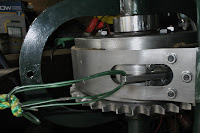
The band brake/ hand brake required more assembly.  Differential + metal band + lining = handbrake.

I pre-assembled the hand brake and noted that:
- the metal band needed to be bent slightly to allow for the bolts on the activation lever to move without scraping the differential braking surface.
- the three mounting screws for the band needed to be tightened so that the band allowed a gap for the drive chain all around.
- I decided to use 8 M5 brass c/s screws, in pairs, to back up the glue.  Like others, I prefer a belt and braces approach.
- I drilled tapping holes in the metal band, while in position, so that I would be confident of a good fit later.  The tapped threads made assembly easier, clamping the lining to the band when the glue had been applied.  This also enabled the use of the nuts to lock the assembled brass screws.
- rather than clamp the lining in place while the glue matured, I assembled the parts in their final position and tightened the brake to provide clamping force.
- I have discovered some useful rope knots: I needed a bowline for the brake activator ( I would rather have used a shackle than garden wire, but needs must). I also used a Trucker's Hitch to tighten the brake.  
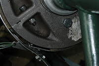

The final assembly showing expressed glue and brass screws with nuts.
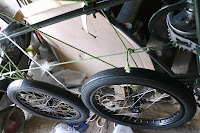


The final picture shows the Trucker's Hitch and the front wheels, just delivered.  
The tyres from Avon are for front wheels of a classic motor bike, rated for 112 mph and a load of over 200kg at 40 psi.  I'm not sure I shall be attempting that sort of speed or load in my vehicle!
Next steps are to get a better coverage and finish on existing paintwork, check the assembly so far, and get on with the front wheels.  For the wheels I shall adjust the steering for zero toe-in/out.

Saturday, 22 July 2017

Differential complete - the pig is tamed


The assembly instructions said that this kit was "a bit of a pig", the pig is now tamed! and I have a fully functional differential.  Pictures do not show much difference, but the work to get it operational has been substantial.

I have used car engine oil for lubrication during trial assembly, to enable assembly and removal of close fitting parts.  I have re-learned how misaligned, close fitting parts can jam if they are forced!  Penetrating oil has had to be used occasionally.
When first received, the two halves of the differential were close fitting and difficult to separate; I have filed some small indentations into one half so that a screwdriver can be inserted to help with separation when that becomes necessary .  There will be plenty of flat surface if I decide to use some sealant to keep grease in, and away from the working surface of the drum brake (the outer circumference of the diff).

I had an “OOPS” moment when I had assembled everything and found eight spacers/washers left over.  The pinions in the differential could move sideways but for the grub screws.  These were re-assembled taking more care to follow the drawings provided and insert the spacers.  Some dexterity was needed to align the through bolt with the spacers.  I found that the bolts are easier to assemble to the spacers if they are passed through the arbor from the pinion end.
While preparing the spur gears for assembly, I noted that only one pair of keys has been supplied, and assume that the spare slot on the shaft is not needed.  I suspect that the same will be true of the wheels themselves.

At the outer end of the half shaft is a length of shaft machined to fit the inside of the wheel.  The inner part of the roller bearing needs to be passed along this part of the shaft, but seems to be an interference fit on it, which presents a challenge to someone without the strength/ equipment/ skill to force it into place.  I am considering the use of some abrasive to ease this fitting.

On a lighter note, the Lykamobile has obtained a nickname of ‘The Wench’, as she is claiming time alone with me in the garage.  As described previously she is suspended from a “Wench Winch”, and my set of spanners has been converted into a set of “Wench Wrenches”.  The least said about ropes and shafts the better, in this context; Shakespeare was much better at that sort of language.  (She is now tied up and shafted).


For my future reference, this is what I have done
Put RH hand shaft in position, this one has tighter fitting parts which are readily assembled on the bench, but can jam on assembly in situ.  With lubrication and care, the inner end parts are pushed into place, in order:
1. Roller bearing inner part
2. Arbor which can be used to prevent the bearing from becoming mis-aligned
3. Differential bearing, over the arbor.
4. Spur gear key
5. Spur gear
6. Spring washer
7. Half nut (hand tighten only!)
In the absence of a wheel on the outer end, a length of 28mm plumbing pipe (about 13.5 cm long), a wide 30mm (Form C) washer and an M16 nut can be used to prevent the shaft going too far in.  On first assembly, tightening the outer nut had  the effect of forcing the inner roller bearing into place against a slight interference fit (I have no idea if it is now removable!)   Thanks to sheddingitall.blogspot.co.uk  for his illustration of a similar arrangement which I have imitated.

The second (left hand) shaft is “a pig” to assemble (quote from assembly instructions)
A diagram for my future reference:


With the spring washer uncompressed there is too little clearance to put the half nut in place. The spring washer is 3.5 mm deep, but 7 mm when not compressed. There is less than 5mm available!

I got an anti-vibration, serrated washer to use if I couldn’t fit the spring washer supplied.  It was not needed.


Then it got greasy!
Re-assembled everything with a liberal coating of grease.  The differential jammed solid when the two halves of the casing were bolted firmly together.  After much thought and experiment, I tracked down the problem to the mounting within the casing being slightly smaller diameter than the plain bearing between the differential casing and the half shaft.  The plain bearing was not only held to the casing but was also clamped to the half shaft.  A Vernier gauge confirmed my theory.  So something like 0.2 mm had to be removed from the bearing mounts on the casing.  Everything now rotates smoothly.


I am considering the addition of spring washers under the nuts which hold the two halves of the differential casing together.  On one side, the chain sprocket is bolted on and should hold it together, but on the RHS, I don't fancy the idea of the bolts vibrating loose.
The screw threads for the through holes into the casing are not long enough, so the bolts will have to be shortened.

The next kit has arrived - the brakes.  As we don't yet have wheels, we will be able to stop before we can go!  There is also painting to catch up on; quite a few knocks and bumps, etc.


Monday, 26 June 2017

Catching up

I am grateful to those who have noticed my absence and have contacted to see if all is well.  I have been delayed from completing the current work on the Lykamobile by family commitments.  To summarise where I have got to now...
I realised that the chassis was going to get a bit heavy, so I have rigged up a suspension system based on a block and tackle (rated at 300kg, so it will take all but the completed car at 400kg).  A sling arrangement allows for 3 degrees of freedom, so I should be able to put the machine at any angle and height.
 With limited width, this might help with some assembly tasks.  Some other builders have more space, experience and materials than I do, so I am keeping tracks on what others are doing or advising.   For example, I am interested in how well sheddingitall.blogspot.co.uk is doing.
I am still fitting and assembling, in preparation for final assembly.  For those who are interested in the less than conventional differential design, here are some pictures of the piece.
  This shows half the differential and the drive chain wheel.  The next picture shows a half shaft with a spur wheel engaging with one pinion mounted in the differential housing.  The second pinion engages with the first, but not with the spur wheel which is offset.


  The same arrangement is used for the other half shaft, allowing the half shafts to counter-rotate via the two pinions..

[to be continued!]