Saturday 2 November 2019

Electrics

I have taken some time out to prepare some electrics, as I have outlined earlier.
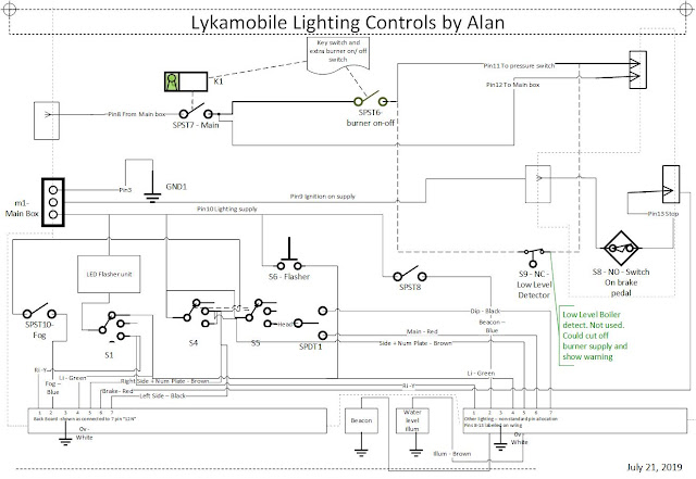
The first picture shows the box provided as part of the Lyka build, together with a lighting control box.  In the photo, the wires are laid out in much the same way as they will be when installed.  I have done as much as I can in the warmth of my study, the next stage is to install them.  The picture shows (top left) that additional wires go to the Lyka control box.  The new lighting control box will be mounted just in front of the reverser/ handbrake quadrant.  Switches are included for:
  •  indicators 
  •  sidelights/ headlights (including water gauge illumination)
  •  dip/ main beam
  •  headlight flasher
  •  rear fog light
  •  beacon (as required for slow moving vehicles on dual carriageways)
  •  burner on/off
  •  key switch to enable all electrics.
A 7-pin connector is used to attach to a trailer lighting board, which can double up as rear lights for the Lyka;  The lighting board is not shown.
A 13-pin connector is used for all other connections to the lighting control box, but not wired in the conventional manner. 

The cables go:
  • from the main box to the lighting box, via the battery and chassis holes, and including lighting power
  • from the main box to the burner, via the chassis
  • from battery to cigarette lighter socket
  • from the main box to the boiler pressure sensor, via the chassis
  • from the lighting box to the forward facing lights (ending in a connector strip at present)
  • from the lighting box to the pressure sensor (making one original wire redundant)
  • from the lighting box to the brake pressure switch fitted to the rh rear caliper
  • from the lighting box to the beacon.

The inside of the lighting box is wired from plugs to switches, as seen.  There is also a LED compatible indicator flasher.  
 The main control box has been modified by inserting a connector strip in series with the main switch so that the key switch can be attached.

I was glad to mainly use crimped or screwed connections, as I do not yet have the skill to solder quickly with modern lead-free solder - I learnt with lead solder half a century ago, and before the awareness of "Hazardous Substances" had raised its head.
As I shall use only LED bulbs, I have used lighter weight wiring, for the reduced current load.

I can no longer put off working outside again!

Tuesday 8 October 2019

Progress

I have received the boiler and the cladding (Kit 18), but without the insulation!
The painting programme is ongoing; so far I have removed the pedals, battery box, towing rings and fuel tank, and repainted the spoilt finish revealed.  Phase one is complete, with the removed components and foremost sections of the chassis re-painted (except the points where the chassis rests on the axle stands), with emphasis on those areas which seemed to be susceptible after last winter in storage.  The battery box can now go back.
Once the battery box is re-fitted, then the electrics and hydraulics can be worked on.  Bleeding the brakes will be high on the list.  With the extras to be added now that we know that there will be a battery, those can be added as described in my earlier post.  The final electrical bits need to be ordered.  The batteries are receiving a periodic charge to keep them in good condition.
I plan to braze up a couple of lanterns and put some LED bulbs in them, I expect to apply that experience to building a steam whistle from plumbing parts.
I was having trouble with the grommets, so have used round grommets cut in half for the ends of the oval cutouts, with the supplied straight sections for the longer sides.
I have an A-Frame towbar to make.
I am not totally convinced that the chimney is an optimal design, although it was good enough for the Stanley brothers. I am thinking that a lower point for the exhaust could be better, with the help of a blast pipe from the engine exhaust feeding into an expanding chimney. Feed water could be pre-heated if water pipes were stuck to the smoke box. I am wondering if a small amount of super-heating could be achieved by brazing some fins onto the steam outlet pipe which crosses the top of the boiler.
No pictures yet, there is nothing presentable to show.

Thursday 1 August 2019

Detection of boiler water levels

I have been thinking about this topic and tried out some ideas:


The Lykamobile series 2 (“Lyka2”) provides for the driver to monitor boiler water levels using the sight glass, in common with established practice for steam engines, steam cars and locomotives.  Modern static steam generating facilities are required to use automatic means for monitoring and responding to boiler water levels.  It is a sensible argument that mobile steam generation should do the same (but don’t push for this as a new regulation to haunt existing steam locomotive users). 

As a desirable objective, the various means of detecting boiler water levels should be considered:

-        - Conductive detection:

-        - Physical level detection;

-        - Capacitive detection;

-        - Optical detection.

Conclusions on the above methods in the context of Lykamobile construction have been subject to my preliminary observations.

1.      Conductive

The original Lykamobile used a set of conductive probes in a separate vertical copper tube, in the position normally used for the optical sight tube, to determine boiler water levels at pre-set points.  The plumbing is an extra for Lyka2.  The electronics is not complex, but requires some expertise for design and assembly.  Some users have reported using spark plugs as suitable detectors, as they isolate the detection probe and provide for a seal against pressure.  I had some left over from the car I maintained 50 years ago!  At room temperature and pressure, their resistance measured >20Mohms when dry and ~400kohms when immersed in water. A simple detection circuit could be arranged to drive the burner relay and a warning light.  I have no information on the electrical characteristics of water and steam at 200+ psi, so cannot assess if my assumptions would be valid.

2.      Physical

a.      Pressure

Some modern systems use a differential pressure monitor to measure water height – I have not investigated this option – it looks a bit complicated for an ”Add-on”

b.     Flotation

It should be possible to attach a magnet to a float in the sight glass (or a copper tube in parallel) , and then use a reed switch to detect the position of the magnet -  no extra plumbing is needed for the sight glass.    I am not sure about the material for the float.  Many plastics sink; others melt at the temperature reached by water boiling at 200+ psi.  When I put expanded polystyrene in my cooker at 220deg C, it started to melt and shrink, but remained buoyant.  Polypropylene (the lid on my Swarfega container) just floats, and seems to have a tolerable melting point.  I would worry about putting plastics in the sight tube;   we could end up with gloop to block the waterways, or re-inventing the 1960s-style lava-lamp but for high pressure boiling water.  Perhaps the plastic could be contained in a metal cap from a water bottle (e.g. tonic – let’s all have a gin and tonic for experimental purposes).  This looks like a possibility.

3.      Capacitive

Some modern systems rely on the capacitive properties of water. I have not investigated. It seems to involve the use of an a.c. detector voltage.

4.      Optical.

Both refractive index and opacity vary between water and steam.  These could be used to trigger a response when a certain water level is reached in the sight tube.


I have found that a glass container will not trigger a response from my battery operated soap dispenser, but when filled with water, the same glass container will set off the trigger.  I can only conclude that the detector and electronics respond to water as if it were opaque – quite possible if the source were an infra-red LED.  To buy and re-work such a dispenser (from Reckitt) might be a solution.  There would be no need to re-work the Lyka2 pressure pipe-work.

If a black and white pattern is placed behind a half-full bottle, then the refractive index of water causes the pattern to move (as in a magnifying glass); careful alignment of an optical detector might be used to measure water level.


Monday 22 July 2019

Towing and Electrics


I have not followed my strategy of building the Lyka without amendments.  
At some stage it will be necessary to tow the Lyka.
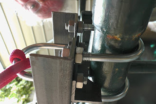
I have added towing points which clamp to the front axle.  A cross bar will take any lateral loads between towing eyes.  The cross bar will also  be useful for mounting any other extras, such as number plate.  The assembly is clamped to the front axle with 2 U-bolts on each side; a further U-bolt on each side serves as a towing eye, which will also take a slowing down force (as trailers under 750kg do not have to be braked). 

General towing point arrangement
Closer view of Left Hand
Side
Views from underneath

Front View

I have tested out the towing arrangement (hence the red rope).  Using a block and tackle, I applied an estimated >300kg (0.5 g) No distortion or breakage occurred.

I have also done some work on a set of electrics.  I shall use modern lighting components, in the interests of safety on modern roads.  They might be disguised as period lamps. I have yet to decide on the physical layout, to be decided by the characteristics of the components.
As a towing bar will be needed, with the regulatory lights, it would make sense to use these on their own for Lyka use.  When unplugged from the towing vehicle, they would be plugged into the lighting control box, to be placed handily for the driver.  I have assumed a 7-pin connection (using an adapter if necessary)


I have added a key driven main switch, in the interests of security; and a burner cut-out switch.  These will entail modification of the original design.


A warning beacon is included, as this is a requirement for vehicles travelling at <25 mph on unrestricted dual carriageways.  I have tried to keep to conventional pin allocation and wire colouring for trailer connections.  As far as low water levels in the boiler are concerned, STW have advised that no additional safeguards are needed beyond those which are provided, to the original design.  Any additional monitoring and safeguarding systems are up to the builder.


Monday 8 July 2019

Engine OK, now to catch up

The engine now turns over, with valve timing achieved and steam chest covers in place.  I have not yet run the engine on compressed air.  The band brake is operational.  All the controls on the quadrant work (brake, valve gear control, water control).  I now need to catch up on the disc brakes and basic electrics.  I have also designed a clamp-on attachment for towing and any front-end extras, providing two u-bolts to act as towing points for an A-frame tow hitch.  I am planning to put in place some modern electrics for lighting, the additional lighting is at the design stage; I shall abandon historical accuracy in favour of safety.  With all the work done to it, the steamer's paintwork is starting to look a bit shabby; there will need to be a programme of re-painting before it is fully presentable.

Thursday 27 June 2019

Oops!

When I was trying to adjust the valve timing, the engine did not turn over for a complete revolution - because I had checked it before installing the piston rod gland filling.  The gland fitting was further out when the filling was installed (of course!) and occupied the space needed for full movement of the piston rod and cross-head.  I now have to dismantle the engine assembly to obtain full access to the gland to check and re-adjust it.  I suppose this will be good practice,   :( .  The engine drops out of the car without much trouble.  I shall, hopefully, also learn to check everything thoroughly as I do the work.

Sunday 16 June 2019

Future plans

I have declined the offer by Steam Traction World to supply me with one of the first batch of ten boilers,  as I have had to share my activities with family centred activities, so have fallen behind in my Lykamobile assembly schedule.
I do have kit of parts for a set of electrics for the steamer, which have prompted me to think about the best arrangement for me.  I would like to be able to control the electrics by using a keyed switch, so that all electrics are off when the key is removed.  I also want to be able to turn off the burner shortly before reaching a destination, so that the energy stored in the boiler can be used and reduce the boiler pressure as the end of a trip comes along (this is recommended practice for other steam vehicles).  As I am hoping to be able to tow the Lykamobile using an A-Frame, then the lighting provided by the towing vehicle should be used by the steamer.  The same lighting should be made available when driving the steamer on its own.  Any legal vehicle designed for lower speeds should have a beacon if driving on dual carriageways. - I expect to be able to use one.
All in all, there is a need for an updated electrical circuit diagram, which I am in the process of producing.
The use of standard caravan connectors would seem to be worth adopting.  I envisage adding an extra box for lighting electrics.
I have been able to procure a set of batteries as recommended by STW, they need to be kept charged.
It would be nice to include an alternator in the design somewhere to enable charging without connecting to the mains, and while running the steamer.  If I achieve that ambition, I can post details in this blog.
For security, I would like to be able to use a padlock to disable the reversing control.
I have got to have a steam whistle, and might be able to build one from standard plumbing materials.

Reversing lever and other controls

The mounting for the reversing lever (and handbrake and water bypass control) is welded to the top right part of the superstructure.  The alignment with the engine, on its vertical pillar, was a bit out - I am assuming that welding and the making of box section tubes is not a precise process.  Compensation for this has been achieved by putting extra washers on the engine mounting bolts, which push the engine forward and upward, by 1 and 3 washers' thickness, respectively.  I had to use my block and tackle to take the weight of the engine while doing that.  The reversing lever shaft can now be bent slightly and gently into alignment.  I thought I might need to use washers under the mounting brackets on the engine, but this was not needed because there was sufficient free play on the mounting bolts (once the paint layer had been removed).
The next job will be to finish the engine timing.  Turning the engine over by hand is proving to be an issue, with the gland packing and piston rings in place and causing resistance.  I have had the kind offer of loan of an air compressor to enable the engine to be powered up and tested, assuming that connections can be made or blanked off. I have been fairly liberal with my oil can, so everything seems to be coated in lubricant.  I wonder if I should invest in some "universal" steam cylinder oil rather than using motor oil designed for internal combustion engines.
 

Engine in place


The engine was painted, as planned, in silver for hot parts, and yellow for moving parts.


T


The engine proved to be quite heavy, but was put into place with the help of a block and tackle.

Wednesday 8 May 2019

Painting the engine

Now that it all fits together, the engine can't be painted without taking it apart again!
It is now split up into sub-assemblies ready to be painted.
I shall use WaxOyl for hidden parts and mating parts where a layer of paint might otherwise upset the spacing achieved without a thick layer of paint.
Silver barbecue paint will be used for surfaces likely to get hot (e.g. cylinders and nearby structures).
I thought yellow would be good for moving parts - I have been aware that there are heavy fast moving parts which could damage the unwary: yellow is a suitable warning colour?  If I have some left over I can use it for lining on the outside panels to provide extra visibility.
The rest will be dark green as before.
Copper and brass may be left untreated and available for polishing.
Parts to be treated will have to be rubbed down and washed (I am reminded of a children's story in which dirty pigs did not want to be washed, and responded to the idea of soap with "Oofy, Poofy, nope")
While re-assembling, steam sealing will take place - valve chest, cylinder ends, inlet and outlet pipe fittings + piston rings, and piston and pump rod glands.  Any parts which might come loose will need to be thread locked or punched into place.
--------
Wed 22nd May
Work in progress.
One side of the engine is painted and re-assembled - this time with piston rings, gland stuffing and "Steam Seal".  I was forgetting how much assembly I had achieved, and now have to repeat! I am so pleased that I had bought a hub puller and other useful tools to help with assembly and dis-assembly.
I wish I had used gloves when handling the Steam Seal; it is designed to withstand hot pressurised steam, and easily resists any attempt to remove it from hands using domestic hot water and soap/ detergent - I suppose I should be pleased that it performs.
I have also filed small slots in the  cylinder end covers so that I can insert a screwdriver to lever off these bits for future maintenance activities.

Picture of completed and painted engine is awaited!

Thursday 2 May 2019

The engine is assembled

Now that I have made everything fit together to form an engine I now have to dis-assemble it for painting/ rustproofing/ sealing.  There are no parts left over. As promised in the assembly instructions, it took a while to get the valve rods lined up with the bearing; I ended up having to make the circular piston mounting holes into slots to enable some sideways movement.  One piston was shimmed out from the central column with washers so that the valve rods were the correct distance apart.  The eccentrics are not yet in place as they need a hub puller to dis-assemble them - I am treating that as a one-off exercise.


 The hot parts will be silver, as I have some high temperature paint that colour.  I was thinking of  painting moving parts a distinctive colour - yellow perhaps?
Everything that can leak steam will need to be sealed.  Inaccessible surfaces will be coated to resist rust.  Glands will be sealed, piston rings are to be fitted.

I have procured some batteries as recommended.  I note that the batteries need to be kept charged to preserve their condition.

If there is a battery, then electric lights are an option - will try to find (or make) some that look as if they come from the right era, but will use LEDs for efficiency and safety. In the short term, some bicycle accessories may be pressed into service.

I have got to have a steam whistle!  According to 19th century legislation, one is not allowed to use a steam whistle so as to frighten animals (e.g. the horses of the Lord of the Manor)

I note that the battery box is watertight, as it was directly under a hole in the tarpaulin when it rained.  A hole will be needed,

Next steps:  fit the disk brakes; fit the controls; wire up the batteries.  That should keep me out of mischief for a while!

Sunday 17 February 2019

Progress

Thank you to all my contacts who were concerned about the absence of posts in this blog.  I have given priority to family matters, so the Lykamobile has been languishing with little attention.
The wild winter winds have played havoc with the tarpaulin, so I must either repair it with duct tape or replace it with something which is fit for purpose ( and more expensive!)
Although I must be well behind some of my more capable fellow builders, I feel that progress is being made.


 The first stage has been reached, with a trial fit of the main moving parts, without piston rings or gland packing.  Bearings were fitted without too much of a problem, once the plain bearings had been put in the freezer for a while.  I had the right tools to drill and tap the mountings for the updated water pump design. I was also reminded from a long time ago the advice that an undersize tapping drill makes the operation much more difficult.  I re-finished the steam ways through the valves, to reduce possible drag.  My biggest challenge was to enable the crank pins through the cross heads to be a good fit without movement but enabling a push fit by hand. 
I also had to avoid screwing the piston rod too far into the crosshead as the small end of the connecting rod wanted to be in the same place.
 The whole thing will need to be dis-assembled, cleaned and painted before putting it back together again, not forgetting to make everything tight and secure - loctite will be good on all but high temperature parts.
I think I shall press on with the next stage before taking anything apart; I really want to see how the 'modified Hackworth' valve gear works in practice.
Putting everything together is a bit like those metal puzzles sometimes found in party crackers.
 As another builder has commented, the engine is getting heavy.  I am using a block and tackle to help me.  I had my eye on some high temperature paint just at the time when Bunnings gave up and sold out to Homebase, so I have stockpiled some cut-price spray cans of paint for the cylinders and anything hot nearby which might need paint.  I was thinking of making a wooden cover for the hot bits, which should reduce heat loss and reduce the risk of getting burnt.  It might help with reducing condensation in the steam ways and cylinders - we don't want hydraulic lock in the cyclinders, although I have been assured that the slide valve to be used does help to minimise the effects.