Thursday, 31 August 2017
More springs
I have now filed down the matching parts so that all tops meet their bottoms. I could not resist the urge to assemble and install the next set of springs without completing the painting on them. I felt as if the builder has been left to bridge the gap between blacksmith and machinist. I have the impression that the leaf springs were made in a hot forge and persuaded to take their shape by a large man with a hammer and anvil. I think that the assembly tolerances are less than those needed for fitting horseshoes.
Friday, 25 August 2017
First spring

I have been thinking about "bolt-ons" while the paint was drying on the leaf springs, and have updated my "Bells and Whistles" page. I have decided to buy a small trailer, before the effects of Brexit make it more expensive.
Monday, 21 August 2017
This could get boring.
I have made 6 half sets of springs, with five items in each. One set is fully painted, the next awaits its final coat, the next two have been de-rusted and washed, one has been scrubbed, and the last is waiting for me to pay it some attention. "Are we nearly there, yet?".
While waiting for paint to dry, I was thinking that it could be useful to combine chocks and a wheel clamp, so that any weakness in the handbrake is allowed for while discouraging other people from making off with the treasured Lyka.
No pictures this time; leaf springs may be necessary, but they don't really get exciting.
Wednesday, 16 August 2017
Words = Work

A careful look at the picture will show the latest delivery unpacked: the leaf springs on the floor. It is suggested in the words that the "parts should be painted before assembly" (another short phrase which means much effort): that means that the thirty leaf spring components must all be de-rusted, chamfered, de-greased and painted. It seems to be taking a long time - thirty times 'a few minutes' seems to be expanding to be quite a while. I am pleased to have selected a more expensive paint which will go direct onto the residual rust, without the need for primer or undercoat. I have also ransacked the wardrobes for old wire hangers which have been bent so as to support the leaves while the paint dries.
 ;
;Wednesday, 9 August 2017
Front wheels and brakes.
I have postponed my painting plans so as to assemble the front wheels and disc brakes; I was forewarned that I might find fitting the disc calliper difficult. I have completed a dry/trial assembly of one side, I shall have to disassemble, re-fit and grease up the assembly.
- The outer races of the wheel bearings were a tight fit in the wheel hub, some abrasive action enabled easier assembly.
- The replacement castle nuts fit (unlike the originals).
- The assembly went smoothly, following the drawings.
- When assembling the disc calliper, I noted that the disc is slightly too far in-board to engage with the unworn disc pads when the calliper is fitted over the bosses for the screw threads in the mounting. When the pads are more worn, the problem would be less severe.
- A shim/ washer placed between the grease seal and the bearing can be used to move the wheel hub out a bit. I used an M15 Form C washer which is 3mm thick, the calliper then fitted over the brake disc! :) This was over-compensating for the offset, and might affect the efficiency of the grease seal and disc pads, and the correct operation of the castle nut.
- When I re-assemble the wheel and disc, I shall try to reduce the thickness of the washer (to 2mm, I think). I shall also follow the suggestion made by STW to file off some or all of the bosses, to enable a bit more play in the calliper mounting. STW may come up with a more elegant solution.
- I might also have to use a Swiss file to take off some material from the castle nut to enable the pin to go through, as there will be less thread than originally intended.
Friday, 4 August 2017
Brakes are done
We got the brakes before the wheels.
The machined parts were de-burred, not for mechanical necessity, but because I don't like being cut and scratched by sharp metal.
The disc calipers went on smoothly. The blank plugs on the calipers were done up tightly, as were the pad retaining pins, so these were loosened and put back in ( I used a spanner on the hex key to save wear and tear on arthritic joints.). Note from the pictures that I have not worked out what is UP and which way is DOWN. I have now put the hydraulic input in the down position, so that the bleed position will be upmost. It is also obvious from my pictures that I shall need to improve the paintwork.


The band brake/ hand brake required more assembly. Differential + metal band + lining = handbrake.
I pre-assembled the hand brake and noted that:


- the metal band needed to be bent slightly to allow for the bolts on the activation lever to move without scraping the differential braking surface.
- the three mounting screws for the band needed to be tightened so that the band allowed a gap for the drive chain all around.
- I decided to use 8 M5 brass c/s screws, in pairs, to back up the glue. Like others, I prefer a belt and braces approach.
- I drilled tapping holes in the metal band, while in position, so that I would be confident of a good fit later. The tapped threads made assembly easier, clamping the lining to the band when the glue had been applied. This also enabled the use of the nuts to lock the assembled brass screws.
- rather than clamp the lining in place while the glue matured, I assembled the parts in their final position and tightened the brake to provide clamping force.
- I have discovered some useful rope knots: I needed a bowline for the brake activator ( I would rather have used a shackle than garden wire, but needs must). I also used a Trucker's Hitch to tighten the brake.

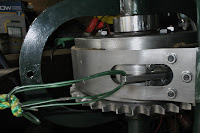
The final assembly showing expressed glue and brass screws with nuts.


The final picture shows the Trucker's Hitch and the front wheels, just delivered.
The tyres from Avon are for front wheels of a classic motor bike, rated for 112 mph and a load of over 200kg at 40 psi. I'm not sure I shall be attempting that sort of speed or load in my vehicle!
Next steps are to get a better coverage and finish on existing paintwork, check the assembly so far, and get on with the front wheels. For the wheels I shall adjust the steering for zero toe-in/out.
Subscribe to:
Comments (Atom)